Network Fundamentals & Protocols Notes#
1. Architecture & Models#
Network Topologies#
Network topology defines the physical or logical layout of interconnected nodes within a network.
- Star Topology: Centralized design where all end nodes connect directly to a central switch or hub.
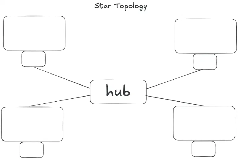
- Pros: Single host failures do not impact the rest of the network; easy to troubleshoot and scale.
- Cons: Central device represents a single point of failure (SPOF).
- Bus Topology: Legacy linear design where all hosts connect to a shared single coaxial cable with end terminators.
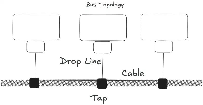
- Pros: Minimal cabling required.
- Cons: Signal reflections occur if terminators fail; main cable break takes down the entire segment; high collision rates.
- Ring Topology: Nodes connect in a continuous closed loop where data travels sequentially in one or both directions (e.g., Token Ring, FDDI).
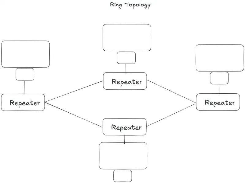
- Pros: Eliminates data collisions via token passing mechanisms.
- Cons: A single node failure breaks the entire ring unless configured as a dual-counter-rotating ring.
- Mesh Topology:
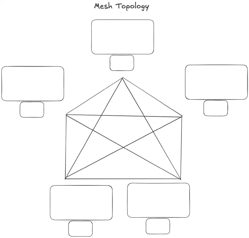
- Full Mesh: Every node maintains a direct physical link to every other node. Formula for required physical links:
N(N - 1) / 2.- Pros: Maximum fault tolerance, link redundancy, and performance.
- Cons: Cost-prohibitive cabling and interface requirements; scales poorly.
- Partial Mesh: Critical core devices maintain redundant interlinks, while edge devices connect via single or dual links to balance cost and redundancy.
- Full Mesh: Every node maintains a direct physical link to every other node. Formula for required physical links:
Duplex & Collision Control#
- Half-Duplex Communications:
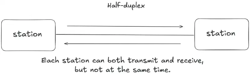
- Devices can transmit and receive data, but not simultaneously on the same channel (e.g., walkie-talkies, legacy Ethernet hubs).
- CSMA/CD (Carrier Sense Multiple Access with Collision Detection): Legacy media access mechanism used in half-duplex Ethernet:
- Carrier Sense: Listen before transmitting to verify the wire is idle.
- Collision Detection: Monitor physical line voltage changes during transmission.
- Backoff Algorithm: If a collision occurs, devices send out a jam signal and enforce a randomized exponential backoff timer before retransmitting.
- Full-Duplex Communications:
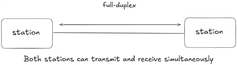
- Devices can send and receive data simultaneously using dedicated transmit and receive paths.
- Switch Execution: Modern full-duplex Ethernet switches eliminate collisions entirely on dedicated point-to-point links, rendering CSMA/CD obsolete in modern LANs.
OSI Model#
The OSI model is a seven-layer conceptual framework created by the International Organization for Standardization (ISO) to standardize network communication.
- Pre-OSI Era: Inter-system communication was complex and fragmented because computer vendors relied on proprietary network implementations.
- Post-OSI Standardization: Manufacturers can design hardware and software for specific layers, passing data sequentially to adjacent upper or lower layers.
- Core Purpose: It serves as a universal, vendor-neutral blueprint that explains theoretical network operations regardless of the underlying hardware or software technology.
graph TD
    subgraph OSI Model [Open Systems Interconnection 7-Layer Model]
      direction TD
        L7[Layer 7: Application Layer
 Protocols: HTTP, DNS, SMTP]
        L6[Layer 6: Presentation Layer
 Functions: Encryption, Formatting]
        L5[Layer 5: Session Layer
 Functions: Connection Management]
        L4[Layer 4: Transport Layer
 Units: Segments / Protocols: TCP, UDP]
        L3[Layer 3: Network Layer
 Units: Packets / Protocols: IP, ICMP]
        L2[Layer 2: Data Link Layer
 Units: Frames / Addressing: MAC]
        L1[Layer 1: Physical Layer
 Units: Bits / Media: Cables, Radio]
    end

    L7 --> L6
    L6 --> L5
    L5 --> L4
    L4 --> L3
    L3 --> L2
    L2 --> L1
TCP/IP Model#
The TCP/IP model is the dominant architecture used in modern networking.
- Layer Consolidation: It combines the OSI model’s Application, Presentation, and Session layers into a single Application Layer, streamlining the framework into 4 (or 5) practical layers.
- Protocol-Driven Design: Unlike theoretical models, it was built around real-world, working protocols (such as TCP and IP).
- Production Backbone: It serves as the actual operational foundation powering today’s global Internet.
Session Multiplexing#
Session multiplexing operates at the Application Layer, enabling multiple independent streams or sessions to run concurrently over a single underlying TCP socket or network connection.
- Handshake Efficiency: Because all logical streams share one established connection, the latency and bandwidth overhead of negotiating repeated TCP and TLS handshakes are eliminated.
- Protocol Adoption: Core implementation strategy used in modern protocols such as HTTP/2, HTTP/3 (via QUIC), and SSH Channel Multiplexing.
- Real-World Application: When a browser opens multiple tabs or fetches dozens of parallel assets from the same domain (e.g., browsing Amazon), session multiplexing prevents connection exhaustion and avoids redundant TLS negotiation overhead.
2. Addressing#
Hardware (MAC) vs. Logical (IP)#
MAC (Media Access Control) Address:
- Layer: Operates at the Data Link layer (Layer 2 of the OSI model).
- Format: 48-bit address represented in hexadecimal format.
- Persistence: Burned into the Network Interface Card (NIC) by the manufacturer. While fixed, modern operating systems (like macOS, iOS, Android, and Windows) use MAC Address Randomization per Wi-Fi network to enhance user privacy and prevent tracking.
- Scope: Local to the Data Link layer (LAN). Used for hop-to-hop frame delivery inside a single broadcast domain. Switches maintain MAC address tables, and hosts use ARP (Address Resolution Protocol in IPv4) or NDP (Neighbor Discovery Protocol in IPv6) to resolve IP addresses to MAC addresses.
- IPv6 Integration: Automatically generates Interface Identifiers (link-local IPv6 addresses) using standard methods like EUI-64 (which embeds the MAC address) or randomized privacy extensions (RFC 4941).
IP (Internet Protocol) Address:
- Layer: Operates at the Network layer (Layer 3 of the OSI model).
- Format:
- IPv4: 32-bit address, formatted as 4 decimal octets separated by dots.
- IPv6: 128-bit address, formatted as 8 groups of hexadecimal digits separated by colons.
- Persistence: Dynamic or static. Automatically assigned by a DHCP server, dynamic ISP pool, or configured manually.
- Scope: Global or routed across logical subnets. Enables end-to-end routing across intermediate network paths and the internet.
IPv4 Network Classes (A, B, C)#
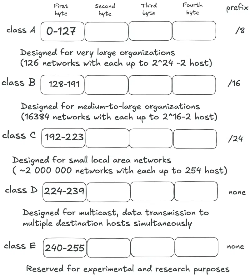
192.168.0.1-254 /24 prefix), making local area networks easy to configure.
Modern Subnetting (CIDR & VLSM)#
While classful addressing provided simple defaults (like home routers defaulting to Class C 192.168.0.0/24), it caused massive address waste. Modern networks use CIDR and VLSM:
VLSM (Variable Length Subnet Masking) Allows network engineers to subdivide an IP address block into subnets of varying sizes based on exact host requirements, rather than applying a single fixed mask across the entire network.
- Optimized Address Utilization: Eliminates wasted IP addresses by matching prefix lengths to host counts (e.g., using a
/30or/31mask for 2-host point-to-point links, vs. a/23mask for a 500-host Wi-Fi network). - Enterprise LAN Subnetting: Allows hierarchical subnet design where different departments or VLANs receive subnets tailored to their size (e.g., Finance gets a
/26, IoT devices get a/24, Router Interlinks get/30s). - Requirements: Requires classless routing protocols (such as OSPF, EIGRP, BGP, or RIPv2) that carry subnet mask information in their routing updates.
- Optimized Address Utilization: Eliminates wasted IP addresses by matching prefix lengths to host counts (e.g., using a
CIDR (Classless Inter-Domain Routing) CIDR replaced legacy classful IP addressing by removing rigid octet boundaries (
/8,/16,/24) and introducing prefix length notation (/X).- Supernetting (Route Aggregation): Combines multiple contiguous smaller networks into a single, broader network prefix (e.g., aggregating four
/24networks—192.168.0.0/24through192.168.3.0/24—into a single192.168.0.0/22route). - Routing Table Optimization: Reduces the size of global internet and enterprise routing tables, leading to faster route lookups and less memory consumption on routers.
- ISP Route Summarization: Allows Internet Service Providers (ISPs) to allocate smaller blocks to clients while advertising only a single aggregated prefix to upstream core networks.
- Supernetting (Route Aggregation): Combines multiple contiguous smaller networks into a single, broader network prefix (e.g., aggregating four
IPv6 Integration & Discovery#
MAC Address Integration in IPv6
- EUI-64 (Extended Unique Identifier): Converts a 48-bit MAC address into a 64-bit interface ID:
- Insert
FF:FEinto the middle of the MAC address. - Invert the Universal/Local (U/L) Bit (the 7th bit of the first byte).
- Prepend
fe80::to complete the Link-Local IPv6 address.
- Insert
Technical NotesUniversal/Local (U/L) Bit:In IEEE 802 MAC addresses,0indicates globally unique and1indicates locally administered. In EUI-64 IPv6 assignments, this bit is inverted for software convenience.FF:FE Identifier:Standard IEEE reserved filler used to expand 48-bit MAC addresses into 64-bit interface IDs without colliding with native 64-bit MACs.Link-Local Gateway (fe80::1):A fully valid, static Link-Local IPv6 address commonly assigned to default gateway router interfaces.- EUI-64 (Extended Unique Identifier): Converts a 48-bit MAC address into a 64-bit interface ID:
Router Solicitation (RS) and Router Advertisement (RA)
Feature / Property Router Solicitation (RS) Router Advertisement (RA) ICMPv6 Type Type 133 Type 134 Sender Host / Client Device Router Destination IP ff02::2(All-Routers Multicast)ff02::1(All-Nodes Multicast) or Unicast to hostTrigger Event Host boots or connects to a new link Sent periodically or in response to RS Primary Purpose Asks on-link routers to identify themselves immediately Announces network prefixes, gateway info, and link parameters Key Payload Info Client Link-Layer (MAC) Address Global Prefix ( 2001:db8::/64), Gateway IP, MTU, SLAAC/DHCPv6 flagsVerification Packet sent without error; host awaits response Host automatically configures a Global Unicast Address (GUA)
3. Address Resolution & Core Protocols#
ARP, RARP, & NDP#
- ARP (Address Resolution Protocol - IPv4): Resolves a known Layer 3 IPv4 address to a Layer 2 MAC address within a local broadcast domain using broadcast requests (
Who has 192.168.1.1?) and unicast replies. - Proxy ARP: Allows a Layer 3 device (like a router or firewall) to answer ARP requests on behalf of a host in a different network or VLAN.
- RARP (Reverse ARP - Legacy): Resolved a known MAC address to an IPv4 address for diskless workstations; replaced by BOOTP and DHCP.
- NDP (Neighbor Discovery Protocol - IPv6): Replaces ARP, ICMP Router Discovery, and Redirects using ICMPv6 messages:
- NS (Neighbor Solicitation - Type 135): Replaces ARP Request via Solicited-Node Multicast.
- NA (Neighbor Advertisement - Type 136): Replaces ARP Reply with target MAC address.
Automatic Private IP Addressing (APIPA)#
When a device is configured for dynamic IP addressing but fails to contact or receive a response from a DHCP server, it automatically self-assigns an address in the reserved APIPA IP range.
- Reserved Subnet Range:
169.254.1.0–169.254.254.255(CIDR:169.254.0.0/16) - Address Generation: The client randomly selects an IP within this block and uses Gratuitous ARP to verify that no other node on the local link is using the same address.
- Scope & Function: Allows link-local communication between hosts on the same physical or virtual layer-2 network segment, but traffic cannot be routed beyond the local subnet or out to the internet without a gateway.
ICMP (Internet Control Message Protocol)#
Operates at Layer 3 alongside IP for operational feedback, error reporting, and testing:
- Type 8 / Type 0 (Echo Request / Echo Reply): Used by
pingfor diagnostic reachability and round-trip time. - Type 3 (Destination Unreachable): Issued when traffic cannot reach a target host, network, or port (e.g., Code 4: Fragmentation Needed with DF set).
- Type 11 (Time Exceeded): Triggered when a packet’s TTL hits 0; utilized by
traceroute/tracertto discover hop paths.
ICMP Architecture & Features#
- Relies on IP Protocol: Encapsulated directly inside standard IP packets (IP Protocol
1for IPv4, Protocol58for IPv6). Operates alongside IP at Layer 3. - No Application Data Payload: Used strictly for diagnostics, path management, and error reporting.
- Connectionless: Operates without handshakes; ICMP error messages can be dropped silently.
- Security Considerations:
- Reconnaissance & Network Mapping: Attackers use ICMP sweeps to discover live hosts and map internal network subnets.
- ICMP Flood (DDoS): Saturates bandwidth and CPU resources by overwhelming targets with massive volumes of ICMP Echo Requests.
- ICMP Redirect Attacks: Attackers spoof ICMP Type 5 (Redirect) packets to trick a host into altering its routing table to route through a malicious gateway.
- Filtering & Mitigation:
- Rate Limiting: Configure edge routers to limit the rate of ICMP traffic to absorb flood attempts.
- Selective Filtering: Block non-essential ICMP types (like ICMP Redirects) at firewall boundaries while permitting essential operational types.
- Ingress/Egress Edge Rules: Drop ICMP Echo Requests from untrusted external WAN networks while allowing internal LAN diagnostics.
Completely blocking all ICMP traffic on a firewall can break critical network operations. For instance, blocking ICMP Type 3 Code 4 (Fragmentation Needed and DF Bit Set) destroys Path MTU Discovery (PMTUD), causing TCP sessions to randomly freeze or drop packets (known as an “ICMP Black Hole”).
Step-by-Step Network Connectivity Troubleshooting#
ping 127.0.0.1(orping ::1): Verifies the local host’s TCP/IP protocol stack, loopback interface, and core drivers.ping <local_ip>: Verifies the local Network Interface Card (NIC) is enabled and assigned an active IP address.ping <default_gateway>: Proves Layer 2 (ARP/MAC) and Layer 3 LAN connectivity to the local router. If this fails, investigate physical links, switch ports, or local ARP tables (arp -a).ping <remote_ip>(e.g.,1.1.1.1): Proves outbound routing, NAT processing, and remote end-to-end IP reachability across external networks.- Check DNS (
ping google.comornslookup): If IP pings succeed but hostnames fail, isolate the issue to DNS server configuration or blocked UDP port 53 traffic.
| Task | Windows Command | Linux / macOS Command | Cisco IOS Command |
|---|---|---|---|
| Interface & IP Config | ipconfig /all | ip a / ifconfig | show ip interface brief |
| ARP Table Inspection | arp -a | ip neighbor / arp -a | show ip arp |
| Trace Packet Path | tracert <target> | traceroute <target> | trace <target> |
| Test DNS Resolution | nslookup <domain> | dig <domain> | nslookup <domain> |
4. Layer 2: Switching & Topologies#
Focuses on frame forwarding, hardware-level performance, and broadcast domain isolation within Local Area Networks (LANs).
Switching Mechanics#
ASIC-Driven Hardware Forwarding:
- Uses Application-Specific Integrated Circuits (ASICs) to perform MAC table lookups and frame forwarding directly in dedicated hardware (silicon) rather than relying on a CPU running software.
- Enables wire-speed forwarding (processing data frames at physical line rate without inducing throughput bottlenecks).
Low-Latency Switching Architectures:
- Cut-Through: Reads only the destination MAC address (first 6 bytes) and immediately begins forwarding the frame before receiving the entire packet. Offers microsecond latency but forwards corrupted frames.
- Store-and-Forward: Buffers the full frame, computes the Frame Check Sequence (FCS) CRC to verify integrity, and drops corrupted frames before forwarding. Standard for modern high-reliability networks.
- Fragment-Free: Reads the first 64 bytes (where most collisions occur) before forwarding, balancing latency and basic error filtering.
MAC Address Table (CAM Table):
- Stores MAC-to-port mappings in Content Addressable Memory (CAM) for instant, single-clock-cycle lookups.
- Learning & Aging: Dynamically populates by reading the source MAC address of incoming frames. Entries age out (typically after 300 seconds of inactivity) to adapt to topology changes.
- Unknown Unicast Flooding: If a destination MAC address is not present in the CAM table, the switch floods the frame out all active ports except the receiving port.
Broadcast Control & Loop Prevention#
Broadcast Storms:
- Occur when redundant Layer 2 links exist without loop prevention protocols.
- Because Ethernet frames lack a Time-to-Live (TTL) field (unlike Layer 3 IP packets), broadcast frames (e.g.,
FF:FF:FF:FF:FF:FFfrom ARP requests) loop infinitely, consuming all switch backplane bandwidth and crashing the network within seconds.
Spanning Tree Protocol (STP / IEEE 802.1D & 802.1w):
- Prevents Layer 2 loops while allowing physical redundancy by logically placing redundant switch links into a Blocking state.
- BPDU (Bridge Protocol Data Units): Switches exchange BPDUs to elect a Root Bridge based on the lowest Bridge ID (Priority + MAC address).
- Path Cost & Port Roles: Non-root switches calculate the lowest root path cost to designate Root Ports, Designated Ports, and Alternate/Blocking Ports.
- Rapid Spanning Tree Protocol (RSTP / 802.1w): Improves convergence times from ~30–50 seconds down to sub-second level via active proposal/agreement handshakes.
STP Enhancements & Layer 2 Performance#
PortFast:
- Function: Bypasses standard STP states (Listening/Learning) to transition access ports directly into the Forwarding state upon linkup.
- Target Devices: Configured exclusively on edge ports connected to end-user devices (workstations, printers, servers).
- Key Benefit: Prevents DHCP request timeouts when a host boots up and eliminates unnecessary Topology Change Notifications (TCNs) across the switch fabric.
- Verification: Check interface STP status to confirm it bypasses listening/learning timers (
show spanning-tree interface <id> portfast).
BPDU Guard:
- Function: Automatically disables a PortFast-enabled port (placing it into an
err-disablestate) if it receives a Bridge Protocol Data Unit (BPDU) frame. - Purpose: Prevents unauthorized switches or rogue routers plugged into wall jacks from taking over the Root Bridge or causing Layer 2 loops.
- Verification: Port immediately enters
err-disablestate upon receiving an unauthorized BPDU (show interfaces status err-disabled).
- Function: Automatically disables a PortFast-enabled port (placing it into an
Virtual Local Area Networks (VLANs) & Management#
Logical Grouping & Micro-segmentation:
- Breaks a single physical switch into multiple isolated broadcast domains logically grouped by function, department, or security level (e.g., Management, Guest, Workstations, IoT), independent of physical location.
VLAN Tagging (IEEE 802.1Q):
- Adds a 4-byte header tag into Ethernet frames travelling across Trunk Links connecting switches or routers.
- Includes a 12-bit VLAN ID (VID) field, supporting up to 4,094 distinct VLANs (
1–4094).
Port Types & Trunking:
- Access Ports: Connect to end-user devices. Carries traffic for a single untagged VLAN; the switch adds the VLAN tag internally and strips it before exiting toward the endpoint.
- Trunk Ports: Connect switch-to-switch or switch-to-router. Carries multiplexed traffic for multiple VLANs using 802.1Q tags.
- Native VLAN: Untagged frames traversing an 802.1Q trunk link are automatically assigned to the designated Native VLAN. Security Risk: Mismatched native VLANs across switches can cause frame leaks and enable VLAN Hopping attacks.
VLAN Trunking Protocol (VTP):
- Function: A Layer 2 messaging protocol that synchronizes VLAN additions, deletions, and renames across switches within a single VTP domain.
- VTP Operating Modes:
- Server: Creates, modifies, and deletes VLANs; advertises changes to the domain (saved to NVRAM).
- Client: Accepts and applies VLAN updates from servers; cannot modify VLANs locally.
- Transparent: Does not synchronize VLAN databases from servers, but forwards VTP advertisements across trunk ports. Allows local VLAN creation.
- Off: Disables VTP processing and forwarding entirely.
- Configuration Revision Number: Every change increments this integer counter. A switch with a higher revision number introduced to a domain will overwrite all other switches’ VLAN databases.
- Best Practice Risk Note: In modern enterprise networks, set switches to Transparent or Off mode to prevent accidental network-wide outages caused by revision number overwrites.
- Verification: Verify revision number and domain name (
show vtp status).
Inter-VLAN Routing Methods:
- Router-on-a-Stick (ROAS): A single physical router interface connects to a switch trunk port using multiple logical subinterfaces, each configured with an 802.1Q encapsulation tag and default gateway IP per VLAN.
- Layer 3 Switch (Multilayer Switching): Routing occurs directly in switch hardware at wire-speed using Switch Virtual Interfaces (SVIs) (
interface vlan X), offering superior throughput compared to ROAS.
Link Aggregation & Bundling#
- EtherChannel / Link Aggregation (IEEE 802.3ad):
- Function: Bundles up to 8 physical Ethernet links into a single logical Port-Channel interface to aggregate bandwidth and provide fault tolerance without triggering STP topology blocks.
- Negotiation Protocols:
- LACP (Link Aggregation Control Protocol): Open-standard protocol (
Active/Passivemodes). - PaGP (Port Aggregation Protocol): Cisco proprietary (
Desirable/Automodes).
- LACP (Link Aggregation Control Protocol): Open-standard protocol (
- Requirements: All physical member interfaces must match in speed, duplex, native VLAN, allowed VLAN range, and trunking configuration.
- Verification: Check summary status of bundled interfaces (
show etherchannel summary).
| Task | Cisco IOS Command | Linux / Cumulus Command |
|---|---|---|
| Inspect MAC Address Table | show mac address-table | ip neighbor / bridge fdb show |
| Verify STP State | show spanning-tree | mstpctl showctl / brctl showstp |
| Check VLAN Configuration | show vlan brief | bridge vlan show |
| Verify VTP Status | show vtp status | N/A |
| Verify EtherChannel Status | show etherchannel summary | teamdctl team0 state |
5. Layer 3: Routing & Forwarding#
Layer 3 focuses on logical IP addressing, path determination across independent subnets, and packet forwarding between networks.
Router Fundamentals#
Broadcast Isolation (Default Behavior):
- Routers do not forward Layer 2 or Layer 3 broadcast frames/packets (e.g.,
255.255.255.255orFF:FF:FF:FF:FF:FF) across interfaces. Every router interface defines a hard boundary for a Layer 2 broadcast domain. - To forward specific broadcast traffic (e.g., DHCP requests across subnets), routers require explicit configuration, such as an IP Helper address (
ip helper-address).
- Routers do not forward Layer 2 or Layer 3 broadcast frames/packets (e.g.,
Unicast Packet Forwarding Logic:
- Layer 2 Decapsulation: Receives an Ethernet frame, checks the Frame Check Sequence (FCS) CRC for errors, and verifies the destination MAC address matches its ingress interface. If valid, it strips the Layer 2 header/trailer.
- Layer 3 Processing: Inspects the IPv4/IPv6 destination address and decrements the Time-to-Live (TTL) or Hop Limit by
1. If TTL reaches0, the router drops the packet and sends an ICMP Type 11 (Time Exceeded) back to the sender. - Routing Table Lookup: Performs a Longest Prefix Match (LPM) search in the Routing Information Base (RIB) / Forwarding Information Base (FIB) to determine the next-hop IP address and egress interface.
- Layer 2 Encapsulation: Resolves the next-hop MAC address using ARP (IPv4) or NDP (IPv6), wraps the IP packet in a new Layer 2 frame with its egress MAC as the source, and transmits it.
Static vs. Dynamic Routing#
Static Routing:
- Pros: Zero CPU/RAM overhead for protocol calculations, conserves link bandwidth (no periodic protocol updates), enhances security by hiding internal network topology.
- Cons: Administrative burden; requires manual configuration for every route change and lacks automatic failover capability without SLA monitoring scripts.
Default Routing (
0.0.0.0/0or::/0):- A special static route (“gateway of last resort”) used when no specific prefix match exists in the routing table. Ideal for edge routers connecting stub networks to an ISP.
Dynamic Routing:
- Protocols automatically discover network topologies, construct routing tables, and recalculate paths when topology changes occur.
- Interior Gateway Protocols (IGP): Operates within a single Autonomous System (AS). Examples: OSPF, EIGRP, IS-IS, RIP.
- Exterior Gateway Protocols (EGP): Operates between different Autonomous Systems across the internet core. Example: BGP (Border Gateway Protocol).
Administrative Distance (AD)#
When a router learns identical routes to the same destination network from different routing sources, it uses Administrative Distance (AD) to judge the trustworthiness of the route source on a scale from 0 to 255. Lower AD values are preferred.
| Route Source | Default AD Value |
|---|---|
| Connected Interface | 0 |
| Static Route | 1 |
| eBGP (External BGP) | 20 |
| EIGRP (Internal) | 90 |
| OSPF | 110 |
| IS-IS | 115 |
| RIP (v1 / v2) | 120 |
| EIGRP (External) | 170 |
| iBGP (Internal BGP) | 200 |
| Unreachable / Untrusted | 255 (Route rejected) |
Dynamic Routing Protocols#
Distance-Vector (RIP v1 / v2):
- Metric: Hop count (maximum
15hops;16indicates infinity/unreachable). - Algorithm: Bellman-Ford algorithm. Periodically broadcasts/multicasts its entire routing table to directly connected neighbors.
- RIPv1 vs. RIPv2: RIPv1 is classful (does not carry subnet masks); RIPv2 is classless, supporting VLSM, CIDR, and multicast updates (
224.0.0.9).
- Metric: Hop count (maximum
Link-State (OSPF - Open Shortest Path First):
- Metric:
Cost= Reference Bandwidth / Interface Speed. - Algorithm: Dijkstra’s Shortest Path First (SPF) algorithm.
- Hierarchy & Area 0: Requires a two-tier hierarchical design. All non-backbone areas must connect directly to Area 0 (Backbone Area) to prevent routing loops between areas.
- DR/BDR Election: On multi-access networks (like Ethernet), OSPF elects a Designated Router (DR) and Backup Designated Router (BDR) to minimize adjacencies and reduce LSA flooding overhead (
224.0.0.6target). - Core LSA Types (Link-State Advertisements):
- Type 1 (Router LSA): Generated by every router to describe its directly connected links within an area.
- Type 2 (Network LSA): Generated by the DR on a multi-access network to list all attached routers.
- Type 3 (Summary LSA): Generated by Area Border Routers (ABRs) to advertise routes between different areas.
- Metric:
Advanced Distance-Vector / Hybrid (EIGRP):
- Metric: Composite metric based primarily on Bandwidth and Delay by default (optionally includes Load and Reliability).
- Algorithm: DUAL (Diffusing Update Algorithm) for instant convergence via precalculated backup paths.
- Key Terms:
- Successor: The primary route with the lowest metric to a destination (placed in the routing table).
- Feasible Successor (FS): A backup route whose reported distance is less than the current Feasible Distance. Promoted instantly if the Successor fails.
- Unequal-Cost Load Balancing: EIGRP is unique because it can load balance across multiple paths with different metrics using the
variancecommand.
Route Redistribution#
- Concept: The process of taking routing information learned from one routing protocol (or static/connected routes) and injecting it into another routing protocol (e.g., redistributing EIGRP routes into a RIP domain).
- Seed Metric Requirement: Routing protocols use different metric calculations (e.g., OSPF cost vs. RIP hop count). When redistributing routes, you must manually define an explicit Seed Metric (default metric) so the receiving protocol knows how to evaluate path cost.
- Redistribution Risks: Can easily introduce routing loops or sub-optimal routing paths if duplicate redistribution points exist without route tagging or filtering.
6. High Availability & WAN Connections#
First Hop Redundancy Protocols (FHRP)#
FHRPs provide high availability for end devices by combining multiple physical routers into a single Virtual Router sharing a virtual IP address and virtual MAC address.
HSRP (Hot Standby Router Protocol):
- Cisco proprietary protocol.
- Operation: Elects one Active router and one Standby router. Traffic actively flows only through the Active router while the Standby remains idle until failure.
- Virtual MAC Format:
0000.0c07.acXX(whereXXis the HSRP group number).
VRRP (Virtual Router Redundancy Protocol):
- Open-standard alternative (IEEE RFC 5798) conceptually similar to HSRP.
- Operation: Elects one Master router and one or more Backup routers. The Master router can use the actual physical interface IP as the virtual IP address.
- Virtual MAC Format:
0000.5e00.01XX.
GLBP (Gateway Load Balancing Protocol):
- Cisco proprietary protocol designed for simultaneous load balancing.
- Operation: Elects an Active Virtual Gateway (AVG) which assigns distinct virtual MAC addresses to up to four Active Virtual Forwarders (AVFs). Inbound ARP requests for the gateway IP are answered with different AVF MAC addresses, balancing host traffic across all routers simultaneously.
WAN Encapsulation Protocols#
PPP (Point-to-Point Protocol):
- Layer 2 WAN encapsulation protocol used over direct serial links. Supports authentication (PAP/CHAP) and multi-protocol compression.
- LCP (Link Control Protocol): Establishes, configures, tests, and terminates the data-link connection (handles link quality and PAP/CHAP authentication).
- NCP (Network Control Protocol): Negotiates higher-layer parameters for specific Network Layer protocols (e.g., IPCP for IPv4, IPv6CP for IPv6).
MLP (Multilink PPP):
- Bundles multiple physical serial links together into a single logical pipe, load-balancing packet fragments across links to increase total bandwidth.
PPPoE (PPP over Ethernet):
- Encapsulates PPP frames inside standard Ethernet frames. Commonly used by ISPs to deliver broadband DSL or Fiber internet connections while allowing endpoint authentication, rate-limiting, and IP address management via standard RADIUS/AAA infrastructure.
7. Network Security & Address Translation#
NAT (Network Address Translation) & PAT (Port Address Translation)#
Purpose & RFC 1918 Private Addressing#
NAT translates private, non-routable IP addresses (RFC 1918) into public, globally routable IP addresses at the enterprise network edge.
- RFC 1918 Private Ranges:
- Class A:
10.0.0.0–10.255.255.255(10.0.0.0/8) - Class B:
172.16.0.0–172.31.255.255(172.16.0.0/12) - Class C:
192.168.0.0–192.168.255.255(192.168.0.0/16)
- Class A:
- Use Cases: Conserves public IPv4 space, shields internal network topology, simplifies ISP migrations without needing internal IP renumbering, and facilitates overlapping network merges.
Pros & Cons of NAT#
- Pros: Extends IPv4 lifespan, hides internal network architecture from external internet visibility.
- Cons: Introduces latency (CPU/memory header rewriting), breaks end-to-end IP traceability, interferes with protocols that embed IP addresses inside application payloads (e.g., SIP, FTP), and complicates IPsec VPN tunnels.
NAT Implementation Types#
- Static NAT (1-to-1): Maps a single internal private IP address permanently to a single public IP address. Used for publicly accessible internal servers (e.g., Web/Mail servers).
- Dynamic NAT (Many-to-Many): Maps internal private IPs to a pool of available public IP addresses on a first-come, first-served basis.
- PAT / NAT Overload (Many-to-1): Maps thousands of internal private IPs to a single public IP address by tracking distinct Layer 4 transport ports (TCP/UDP source port mapping). Supports up to ~65,000 concurrent socket sessions per public IP.
Terminology Mapping#
| Term | Definition |
|---|---|
| Inside Local | The real IP address assigned to a host on the internal private network (e.g., 192.168.1.50). |
| Inside Global | The public IP address representing the internal host to the outside world (e.g., 203.0.113.5). |
| Outside Local | The IP address of an external host as seen by the internal network. |
| Outside Global | The actual real public IP address assigned to a host on the external network (e.g., 8.8.8.8). |
Access Control Lists (ACLs) & Wildcard Masks#
ACLs are sequential lists of permit or deny conditions applied to router interfaces to filter traffic based on packet headers. All ACLs end with an implicit deny all rule.
Wildcard Mask Logic:
- Used in IPv4 ACLs and OSPF network statements to define matching criteria.
- Bit Rule: A binary
0bit means “must match exactly,” whereas a binary1bit means “ignore this bit (wildcard).” - Example: Subnet mask
255.255.255.0corresponds to Wildcard Mask0.0.0.255.
ACL Types:
- Standard ACLs (Numbers 1–99 & 1300–1999):
- Filters traffic based only on Source IP address.
- Placement Rule: Apply as close to the destination as possible.
- Extended ACLs (Numbers 100–199 & 2000–2699):
- Filters based on Source IP, Destination IP, Protocol type (TCP/UDP/ICMP), and Port numbers (e.g., HTTP port 80, SSH port 22).
- Placement Rule: Apply as close to the source as possible.
- Named ACLs:
- Uses descriptive alphanumeric names (
ip access-list extended BLOCK_GUEST), permitting editing of specific sequence lines.
- Uses descriptive alphanumeric names (
- Standard ACLs (Numbers 1–99 & 1300–1999):
Directionality & Management Access:
- Inbound ACL: Filters traffic entering the interface before routing lookups occur.
- Outbound ACL: Filters traffic after routing lookups occur, right before packets exit the interface.
- Management Access (Access-Class): Applied to VTY lines (
access-class <ACL> in) to restrict incoming SSH/Telnet management connections to trusted administrator IP addresses only.
Threat Prevention & Infrastructure Defense#
Blocking Spoofed IPs (uRPF - Unicast Reverse Path Forwarding):
- Prevents external attackers from forging internal source IP addresses. The router checks if the source IP of an incoming packet matches a valid route entry in its FIB for that receiving interface; if not, the packet is dropped.
TCP SYN Flood Mitigation:
- Attackers flood servers with
SYNconnection requests without completing the 3-way handshake (ACK), exhausting state tables. - Mitigation: Enable TCP SYN Cookies or configure Firewalls/Load Balancers to act as proxy handshakes before forwarding valid connections to internal servers.
- Attackers flood servers with
Smurf Attack Mitigation:
- An amplification DDoS attack where ICMP Echo Requests with a spoofed target source IP are sent to a network’s broadcast address, causing all hosts to flood the victim with replies.
- Mitigation: Disable IP directed broadcasts on router interfaces (
no ip directed-broadcast).
Port Security & Layer 2 Inspection#
Port Security (Switch Interfaces):
- Limits MAC addresses allowed on individual switch ports to block unauthorized devices.
- Sticky MAC: Dynamically learns MAC addresses and saves them into the running configuration.
- Violation Modes:
Protect: Drops unauthorized frames silently.Restrict: Drops unauthorized frames and logs an SNMP trap/syslog alert.Shutdown(Default): Immediately disables the port (err-disablestate) and logs an alert.
DHCP Snooping:
- Mitigates Rogue DHCP Server and DHCP Starvation attacks.
- Classifies switch ports into Trusted (connected to legitimate DHCP servers/uplinks) and Untrusted (connected to end-user devices). Untrusted ports are blocked from sending DHCP Offer or ACK messages.
- Builds a DHCP Snooping Binding Database mapping Client MAC addresses, IP addresses, Lease times, and VLAN IDs.
Dynamic ARP Inspection (DAI):
- Prevents ARP Poisoning / Man-in-the-Middle (MitM) attacks.
- Intercepts ARP requests and replies on untrusted ports and validates the IP-to-MAC binding against the DHCP Snooping Binding Database. Invalid ARP packets are dropped.
AAA Centralized Authentication: RADIUS vs. TACACS+
| Feature / Attribute | RADIUS | TACACS+ |
|---|---|---|
| Standard / Origin | Open Standard (RFC 2865) | Cisco Proprietary |
| Transport Protocol | UDP (Ports 1812/1813) | TCP (Port 49) |
| Payload Encryption | Encrypts only the password | Encrypts the entire packet body |
| AAA Architecture | Combines Authentication & Authorization | Completely separates Authentication, Authorization, and Accounting |
| Command Control | Limited command-by-command authorization | Granular command-by-command restriction per user level |
- SNMPv3:
- Replaces legacy unencrypted SNMPv1/v2c (which sent community strings in plaintext) by adding User-based Security Model (USM) providing Authentication (HMAC-SHA) and Encryption (AES).
| Task | Cisco IOS Command | Linux Command |
|---|---|---|
| Inspect Routing Table | show ip route | ip route / route -n |
| Verify NAT Translations | show ip nat translations | conntrack -L / iptables -t nat -L |
| Verify DHCP Snooping | show ip dhcp snooping binding | cat /var/lib/dhcp/dhcpd.leases |
| Check Interface ACLs | show ip interface | iptables -L -v -n / nft list ruleset |