Memory Management #
Memory Addressing #
Real Mode #
In Real Mode, an Intel CPU can only address the first 1 MB of memory space.
- Default Operation Mode: The initial boot state for x86 microprocessors.
- Backward Compatibility: Ensures legacy application software written for the 8088/8086 can still run.
- Conventional Memory: The first 1 MB region is maintained for real-mode execution and backward compatibility.
Protected Mode #
Conventional Memory: The first 1 MB region is maintained for real-mode execution and backward compatibility.
Address Translation Pipeline #
The translation process operates in a two-stage mechanism inside the Memory Management Unit (MMU):
flowchart LR
    subgraph MMU ["Memory Management Unit"]
        direction LR

        %% Inputs
        Selector["Segment Selector"]
        Offset["Offset"]

        %% Mechanisms
        Seg["Segmentation\nMechanism"]
        Page["Paging\nMechanism"]

        %% Final Output
        PA["Physical Address"]

        %% Flow Connections
        Selector --> Seg
        Offset --> Seg

        Seg -->|"Linear Address"| Page
        Page --> PA
    end
- Logical Address: The combined
Selector : Offsetpair (16-bit selector + 16/32-bit offset) fed into the Segmentation Mechanism. - Linear Address: The address output by the Segmentation Mechanism. This acts as the input logical address (32/64-bit) for the Paging Mechanism, which translates it to the final Physical Address in RAM.
Segmentation Mechanism #
The Segmentation Mechanism converts a logical address into a linear address.
Core Components & Addressing Concepts #
The Segmentation Mechanism converts a logical address into a linear address.
- Segment Selectors: The
Selectoris provided directly by a dedicated Segment Register (e.g.,CS,DS,SS,ES,FS,GS). - Linear (Flat) Memory Space: Segmentation maps segment offsets into a linear address space. To the executing program, memory appears as a single continuous address space.
- Abstraction from Physical Hardware: The generated linear address does not directly access physical RAM. While it behaves logically as an address, its actual physical location in hardware cannot be determined without the subsequent Paging Mechanism.
If paging is disabled, 1 Linear Address maps to 1 Physical Memory Address. When paging is enabled, linear addresses are dynamically translated into scattered pages in physical RAM.
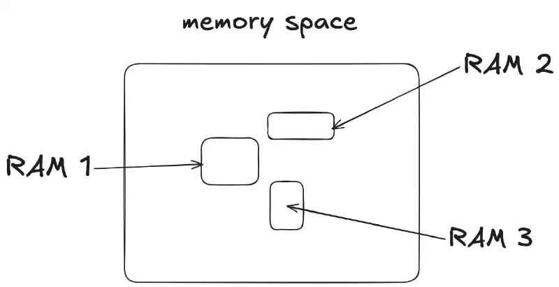
Memory Space Abstraction #
Segmentation in Protected Mode #
In Protected Mode, segment registers store far more information than simple base addresses. Instead of directly holding a physical address, a 16-bit segment register holds a Segment Selector that indexes into a descriptor table.
16-Bit Segment Selector Structure #
The 16-bit selector value is divided into three distinct bit fields:
| Bit Range | Field Name | Description |
|---|---|---|
| Bits 15–3 | Index (Selector) | Selects one of $2^{13} = 8192$ descriptors in the table. |
| Bit 2 | TI (Table Indicator) | Specifies the target table: 0 = Global Descriptor Table (GDT), 1 = Local Descriptor Table (LDT). |
| Bits 1–0 | RPL (Requested Privilege Level) | Specifies the privilege level of the requester (0 to 3). |
Privilege Levels (RPL / CPL) #
Intel x86 hardware enforces privilege isolation using four hierarchical privilege rings:
- Ring 0 (Kernel/OS Core): Private OS functions, core kernel execution, and direct hardware access.
- Ring 1 (OS Services): System services (e.g., networking stack initialization, system services).
- Ring 2 (Device Drivers): Low-level driver execution (e.g., Wi-Fi, GPU drivers).
- Ring 3 (Userland): User application programs and userland processes.
Segment Descriptors #
A Segment Descriptor is an 8-byte data structure inside memory that defines the characteristics of a specific memory segment:
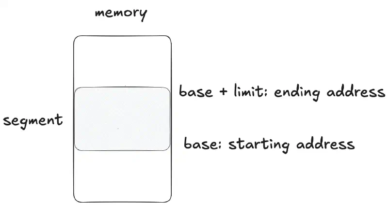
- Base Location: Where the segment starts in linear memory.
- Segment Limit: The total length/size of the segment.
- Access Rights & Attributes: Privilege requirements (DPL), execute/read/write permissions, and segment types.
Descriptor Tables #
Segment descriptors are organized into two primary table types:
- Global Descriptor Table (GDT): Contains descriptors accessible by all programs across the system.
- Local Descriptor Table (LDT): Contains descriptors unique to a specific application or task, providing process-level memory isolation.
Segment Descriptors #
A Segment Descriptor is an 8-byte (64-bit) data structure inside the descriptor table that defines a segment’s starting physical location, boundary size, and security permissions.
Descriptor Fields Overview #
| Field | Size | Description |
|---|---|---|
| Base Address | 24-bit / 32-bit | Starting physical location in RAM |
| Segment Limit | 16-bit / 20-bit | Specifies segment size |
| Access Rights | 1 Byte | Controls privileges and permissions |
| Control Bits | Flags | Granularity (G), Default (D), Available (AV) |
Architectural Evolution: 80286 vs. 80386+ #
- 80286 Architecture (16-bit Protected Mode)
- Base Address: 24 bits (3 bytes total, spanning bits 16–39 of the descriptor).
- Maximum physical memory = 2^24 bytes = 16 MB
- Segment Limit: 16 bits (2 bytes total, spanning bits 0–15).
- Maximum segment size = 2^16 bytes = 64 KB
- Base Address: 24 bits (3 bytes total, spanning bits 16–39 of the descriptor).
- 80386+ Architecture (32-bit Protected Mode)
- Base Address: Expanded to 32 bits (4 bytes total, split across bits 16–39 and bits 56–63).
- Maximum addressable memory = 2^32 bytes = 4 GB
- When G = 1 (4 KB Granularity): The limit is scaled by shifting left by 12 bits (appending FFF in hex).
- Maximum segment size = 2^20 × 4 KB = 4 GB
- Base Address: Expanded to 32 bits (4 bytes total, split across bits 16–39 and bits 56–63).
granularity allows applications (such as high-resolution graphics drivers or video games) to allocate massive contiguous memory segments (up to 4 GB) in 4 KB increments.
Key Control Flags #
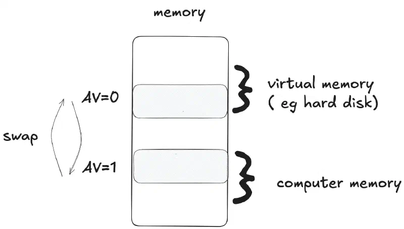
- AV Bit (Available for System): Used by operating systems to track segment usage or mark whether a segment is currently available in physical RAM.
- D Bit (Default Operation Size): Dictates code execution mode inside the segment:
- D = 0: 16-bit instructions (legacy compatibility).
- D = 1: 32-bit instructions (protected mode execution).
Segment Access Rights & Conforming Code Segments #
The Access Rights Byte inside a segment descriptor determines the type of memory segment, its direction/conformance, and read/write/execute permissions.
Access Rights Bit Decoding #
| E | ED/C | R/W | Type | Meaning |
|---|---|---|---|---|
| 0 | 0 | 0 | Data | Read-Only |
| 0 | 0 | 1 | Data | Read/Write |
| 0 | 1 | 0 | Stack | Read-Only |
| 0 | 1 | 1 | Stack | Read/Write |
| 1 | 0 | 0 | Code (Non-conforming) | Execute-Only |
| 1 | 0 | 1 | Code (Non-conforming) | Execute/Read |
| 1 | 1 | 0 | Code (Conforming) | Execute-Only |
| 1 | 1 | 1 | Code (Conforming) | Execute/Read |
- E (Executable):
0= Data/Stack segment,1= Code segment. - ED/C (Expansion Direction / Conforming):
- For Data/Stack (
E=0):0= Expands up (Data),1= Expands down (Stack). - For Code (
E=1):0= Non-conforming,1= Conforming.
- For Data/Stack (
- R/W (Read/Write):
- For Data/Stack (
E=0):0= Read-Only,1= Read/Write. - For Code (
E=1):0= Execute-Only,1= Execute/Read.
- For Data/Stack (
Code Segment Execution: Conforming vs. Non-Conforming #
1. Conforming Code Segments #
Conforming code segments allow code sharing across different privilege levels. They are used when you have utility code that needs to be accessed by applications operating at multiple privilege levels (e.g., system call helpers or math libraries).
- Execution Behavior: The code executes at the Current Privilege Level (CPL) of the caller, rather than switching to the Descriptor Privilege Level (DPL) of the target segment.
- Privilege Rule: CPL != DPL (specifically, CPL >= DPL).
2. Non-Conforming Code Segments #
Non-conforming segments enforce strict memory isolation. Transfers of control occur directly to another code segment using instructions like CALL or JMP.
- Execution Behavior: Source and destination code segments must operate at identical privilege levels. Direct transfer across different privilege levels is blocked by hardware unless routed through a Call Gate.
- Privilege Rule: CPL = DPL.
- Non-conforming: Allows direct transfer only when privilege levels match (CPL = DPL). To cross privilege boundaries, execution must go through the OS using a Call Gate.
- Conforming: Allows code at lower privilege levels to execute higher-privilege code directly, but execution runs under the caller’s lower privilege level (CPL).
Segment Selector Addressing Example #
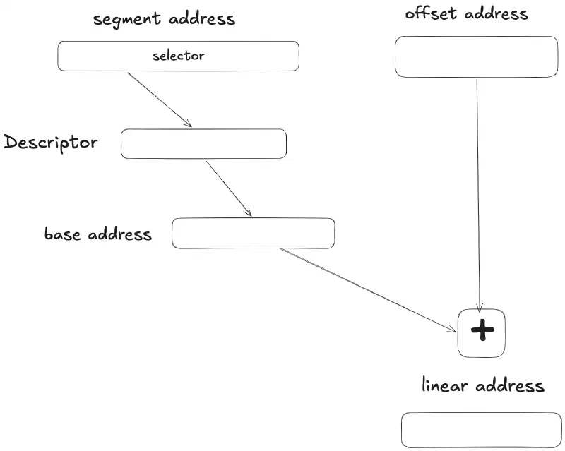
In Protected Mode, segment registers hold a 16-bit Segment Selector that references an entry in a descriptor table, rather than a physical base address directly.
Step-by-Step Translation Walkthrough #
Consider the assembly instruction:
MOV AX, [2H] ; Read memory from offset 2H relative to DS- Selector Decoding (DS = 0008H) Convert the hexadecimal selector value 0008H into its 16-bit binary representation:
0000 0000 0000 1 | 0 | 00
└───────┬──────┘   │   └── RPL = 00 (Ring 0 / Kernel Privilege)
        │          └────── TI  = 0  (Global Descriptor Table - GDT)
└───────────────── Index = 1 (Selects Descriptor 1)-
Index: 1 (References Descriptor #1 in the table)
-
Table Indicator (TI): 0 (GDT selected)
-
Requested Privilege Level (RPL): 0 (Ring 0 access)
- Descriptor Lookup & Field Parsing The MMU retrieves Descriptor 1 from the GDT:
Descriptor 1: 0000 9210 0000 00FF (8 bytes)Extracting the metadata fields yields:
- Base Address: 100000H
- Segment Limit: FFH (Total segment size = FFH + 1 = 100H = 256 bytes)
- Access Rights Byte: 92H
Decoding 92H in binary (1001 0010b):
| Bit Position | Bit Value | Field | Meaning |
|---|---|---|---|
| 7 | 1 |
Present Bit (P) | Valid segment (Present in memory) |
| 6–5 | 00 |
DPL | Descriptor Privilege Level = Ring 0 |
| 4 | 1 |
System Bit (S) | Code/Data Descriptor (Non-system) |
| 3–0 | 0010 |
Type | Data Segment, Read/Write access |
- Linear Address Calculation The final linear address is generated by adding the segment base address to the instruction offset Linear address = base address + offset Linear address = 100000H + 2H = 100002H
Before accessing memory, the MMU verifies whether the offset (2H) exceeds the segment limit (FFH). Since 2H ≤ FFH, memory access is allowed without triggering a general protection fault (GP).
Comparison: Real Mode vs. Protected Mode #
The primary difference between Real Mode and Protected Mode lies in how memory addresses are resolved and how many memory accesses are required for a single operation.
| Feature | Real Mode | Protected Mode |
|---|---|---|
| Addressing Method | Direct calculation (Segment * 10H + Offset) |
Indirect lookup via Descriptor Tables |
| Memory Access Count | 1 Access (Direct physical fetch) | 2 Accesses (Descriptor lookup + Memory access) |
| Address Space | 1 MB (20-bit physical bus) | 4 GB (32-bit linear address space) |
| Security & Isolation | None (Any process can access any memory) | Enforced via Descriptor Privilege Levels (RPL/DPL) |
The Memory Access Overhead Problem #
In Real Mode, calculating an address is extremely fast because the CPU computes the physical address directly using a single shift-and-add operation:
Physical address = (segment register × 16) + offset
Because the segment register directly reflects the physical location, execution requires only 1 memory access.
In Protected Mode, memory addressing becomes an indirect two-step process:
- Step 1 (Descriptor Fetch): The CPU uses the Segment Selector inside the segment register to look up the Segment Descriptor in the GDT/LDT in physical RAM.
- Step 2 (Data Fetch): The CPU extracts the Base Address, verifies access permissions and segment limits, calculates the Linear Address (Base + Offset) and fetches the actual target data.
This indirect lookup creates a double overhead (two memory access cycles for every single instruction or data read).
Solution: Invisible (Shadow) Registers #
To eliminate the double memory access penalty, modern x86 processors implement Invisible Registers (also known as Shadow Registers or Descriptor Caches).
- Mechanism: Every visible segment register (
CS,DS,SS,ES,FS,GS) as well as system segment registers likeTR(Task Register) andLDTR(LDT Register) is paired with a hidden, non-programmable cache register. - Execution Flow:
- When a new Segment Selector is loaded into a segment register (e.g., via
MOV DS, AX, a farJMP, or usingLTRto loadTR), the CPU automatically fetches the corresponding 8-byte descriptor from the GDT/LDT once and caches its Base Address, Limit, and Access Rights into the invisible register. - Subsequent memory accesses or system operations (e.g., fetching task stack pointers from the TSS) read directly from the high-speed invisible register cache instead of re-querying RAM.
- When a new Segment Selector is loaded into a segment register (e.g., via
- Result: Address translation drops back down from 2 memory accesses to 1 memory access, restoring peak hardware execution speed while maintaining full memory protection.
By combining descriptor tables with 32-bit segment limits, x86 Protected Mode achieves a massive theoretical virtual address space:
8192 descriptors x 2 descriptor tables (GDT & LDT) x 4 GB segment size = 64 TB (2^46 bytes)
This total virtual address space of 64 TB is over 60 million times larger than the 1 MB limit of Real Mode.
Paging Mechanism #
Paging performs linear to physical address translation. allows any program and data to be relocatable 1 to 1 mapping
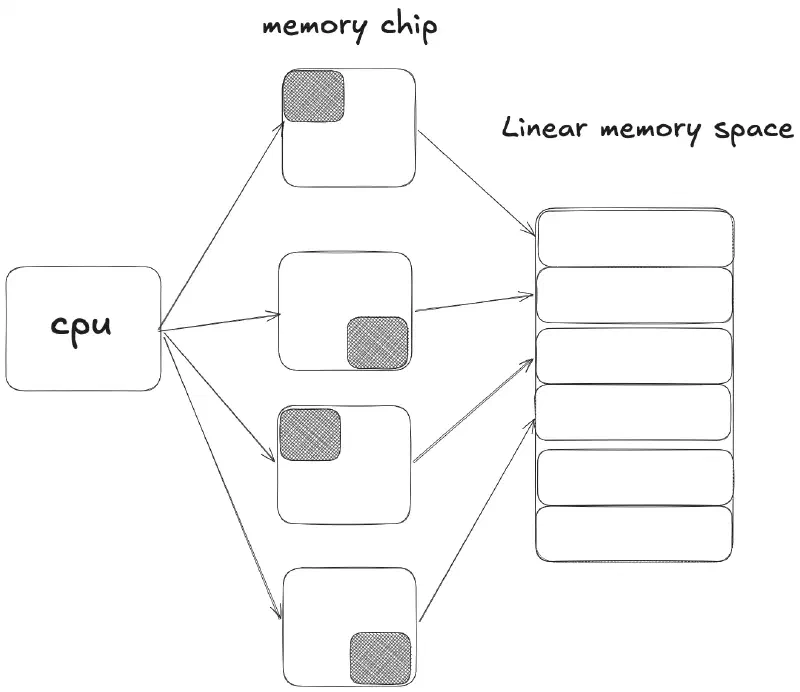
Linear address to physical address #
A 32-bit linear address is divided into 3 fields: dir, page and offset
| Field | Bit Positions | Width | Function |
|---|---|---|---|
| Directory (dir) | Bits 31–22 | 10 bits | Index into the Page Directory (0–1023) |
| Page Table (page) | Bits 21–12 | 10 bits | Index into the Page Table (0–1023) |
| Offset | Bits 11–0 | 12 bits | Byte offset inside the 4 KB physical page (0–4095) |
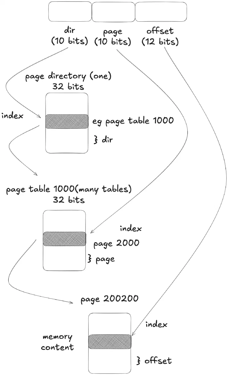
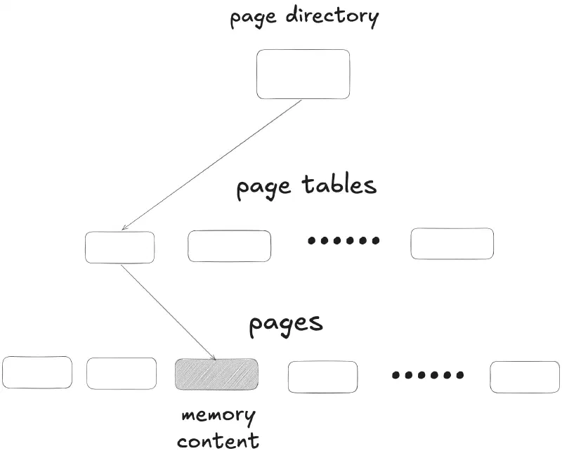
1. Step-by-Step Breakdown of 00F23000H: #
- Convert Hexadecimal to 32-Bit Binary:
00F23000H --> 0000 0000 1111 0010 0011 0000 0000 0000_2 - Split into Bit Groups:
0000 0000 11 | 11 0010 0011 | 0000 0000 0000 └─────┬────┘ └─────┬──────┘ └──────┬───────┘ │ │ └── Offset (Bits 11–0) │ └──────────────────── Page (Bits 21–12) └─────────────────────────────────── Dir (Bits 31–22) - Convert Binary Groups back to Hexadecimal/Decimal:
- Directory (dir): 0000 0000 11_2 = 3H (3 in decimal)
- Page Table (page): 11 0010 0011_2 = 323H (803 in decimal)
- Offset: 0000 0000 0000_2 = 0H (0 in decimal)
2. How to Get the Starting Address of the Page Directory #
The starting address of the Page Directory is derived directly from the CR3 Control Register (Page Directory Base Register).
CR3 Bit Layout
#
CR3 contains a 20-bit Base Address (Bits 31–12) and 12-bit Control Flags/Reserved bits (Bits 11–0).
31                                12 11          0
┌───────────────────────────────────┬────────────┐
│     Page Directory Base Address   │ Flags/Zero │
└───────────────────────────────────┴────────────┘
               20 bits                 12 bits
Calculating the 32-Bit Starting Address #
Because page directories are always 4 KB aligned (4096 bytes = 1000H), the lower 12 bits of the starting address are always zero (000H).
To obtain the full 32-bit physical base address from CR3, use either of these equivalent methods:
- Shift Left by 12 Bits (Bitwise):
Starting Address = CR3 Base Address << 12 - Multiply by 1000H (Hexadecimal Arithmetic):
Starting Address = CR3 Base Address x 1000H
If CR3 contains 00020005H:
- Extract the Upper 20 Bits (Base Address): 00020H
- Multiply by 1000H (or append 000H to the end):
Starting Address of Page Directory = 0 0020H x 1000H = 0002 0000HPaging Registers #
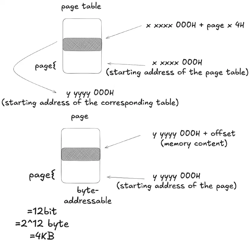
When two-level paging is enabled in 32-bit x86 Protected Mode, resolving a linear address to a physical memory address requires navigating a hierarchy of structures.
-
Step 1 (Page Directory Entry Lookup):
- The MMU multiplies the Directory Index (
dir) by 4 bytes (4H) because each entry in the Page Directory is 32 bits wide. - It adds this result to the Page Directory Base Address (derived from
CR3) to find the Page Directory Entry (PDE).
- The MMU multiplies the Directory Index (
-
Step 2 (Page Table Entry Lookup):
- The MMU extracts the base address of the Page Table from the PDE.
- It multiplies the Page Table Index (
page) by 4 bytes (4H) because each entry in the Page Table is 32 bits wide. - It adds this result to the Page Table Base Address to find the Page Table Entry (PTE).
-
Step 3 (Physical Memory Access):
- The MMU extracts the 20-bit physical page frame base address from the PTE.
- It adds the 12-bit Offset from the original linear address to compute the exact Physical Address.
- Finally, the target data byte or word is fetched from physical RAM.
Without hardware acceleration, translating a linear address to physical memory requires 3 full RAM accesses for every single instruction or data load. This introduces a significant time overhead, tripling memory latency for every CPU operation.
Hardware Solution: Translation Lookaside Buffer (TLB) #
To eliminate the 3x memory latency penalty during repaging of 4 KB pages, modern x86 processors implement an associative hardware cache called the Translation Lookaside Buffer (TLB).
- Purpose: Stores recent linear-to-physical address translations directly on the CPU silicon to reduce translation latency.
- Locality of Reference: Programs frequently execute code sequentially or access contiguous data structures within the same 4 KB page. Once a page translation is cached, subsequent accesses to nearby addresses within the same page result in a TLB Hit.
- Performance Impact:
- TLB Hit: Address translation occurs in 0 additional memory cycles, bypassing both Page Directory and Page Table lookups in RAM (reducing total reads back down from 3 to 1 physical memory access).
x86 Two-Level Paging Address Translation Walkthrough #
Linear Address Breakdown #
logical address = 0080 1000H
0000 0000 10 | 00 0000 0001 | 0000 0000 0000
└─────┬────┘   └─────┬──────┘   └──────┬───────┘
      │              │                 └── Offset = 0H
      │              └──────────────────── Page = 1H
└─────────────────────────────────── Directory = 2H- Directory (dir): 2H (Bits 31–22)
- Page (page): 1H (Bits 21–12)
- Offset: 0H (Bits 11–0)
Step 1: Locate the Page Directory Entry #
- Page Directory Base Address: Retrieved from the CR3 register:
- CR3 Base Address = 00010H
- Starting address of the Page Directory = 00010000H
- Address of Page Directory Entry 2:
- Address of Entry 2 = 00010000H + 2 x 4H = 00010008H
Step 2: Locate the Page Table Entry #
- Fetch Page Table Base Address:
- At memory location 10008H, bits 12–31 contain 00020H.
- Starting address of the Page Table = 00020000H.
- Address of Page Table Entry 1:
- Address of Entry 1 = 00020000H + 1 x 4H = 00020004H
Step 3: Calculate the Physical Memory Address #
- Fetch Physical Page Base Address:
- At memory location 20004H, bits 12–31 contain 00080H.
- Starting address of the physical page = 00080000H.
- Calculate Final Physical Address:
- Physical address = Page base address + Offset
- Physical address 00080000H + 0H = 00080000H
Entry Size Reminder
Each entry in both the Page Directory and Page Table occupies 4 bytes (32 bits). This is why directory and page indices are multiplied by 4H (2 x 4H and 1 x 4H) to compute memory offsets.
Byte-Addressable Memory Decomposition (Little-Endian) #
In 32-bit x86 architecture, memory is byte-addressable, but data bus transfers often read or write in 32-bit (4-byte) aligned words.
The breakdown below shows how a 32-bit memory word stored at address 0000 3FF0H is mapped into individual byte addresses using x86 Little-Endian byte ordering (where the least significant byte is stored at the lowest address).
32-Bit Word Memory Mapping #
| Memory Address | 32-Bit Word Content |
|---|---|
0000 3FF4H |
0003 D003H |
0000 3FF0H |
0003 C003H |
Byte-Level Address Breakdown (0000 3FF0H - 0000 3FF3H)
#
Expanding the 32-bit word 0003 C003H stored at aligned base address 0000 3FF0H:
| Byte Address | Stored Byte | Significance |
|---|---|---|
0000 3FF3H |
00H |
Most Significant Byte (MSB) |
0000 3FF2H |
03H |
Byte 2 |
0000 3FF1H |
C0H |
Byte 1 |
0000 3FF0H |
03H |
Least Significant Byte (LSB) |
Paging Address Translation Example (000C8000H)
#
This step-by-step example demonstrates two-level address translation for linear address 000C8000H.
1. Linear Address Field Parsing #
Linear Address: 000C8000H
Converting to 32-bit binary:
0000 0000 00 | 00 1100 1000 | 0000 0000 0000
└─────┬────┘   └─────┬──────┘   └──────┬───────┘
      │              │                 └── Offset = 0H
      │              └──────────────────── page   = C8H
└─────────────────────────────────── dir = 0H- Directory (dir): 0H (Bits 31–22)
- Page Table (page): C8H (Bits 21–12)
- Offset: 0H (Bits 11–0)
2. Locate Page Directory Entry #
- Page Directory Base Address:
- Retrieved from register CR3.
- From CR3, the top 20 bits specify base address 2000H (or full 32-bit address 00002000H).
- Address of Page Directory Entry 0:
- Entry address = 2000H + (0 x 4H) = 2000H
- Read Page Directory Entry Content:
- Memory location 2000H contains 00003003H.
- Lower bits breakdown: W = 1 (Writable), P = 1 (Present).
- Extract upper 20 bits for the Page Table base address: 00003000H.
3. Locate Page Table Entry #
- Address of Page Table Entry C8H:
- Offset Calculation: C8H x 4H= 1100,1000 « 2 = 1100,1000,00 = 320H
- Entry address = 0000 3000H + (C8H x 4H) = 0000 3320H
- Read Page Table Entry Content:
- Memory location 3320H contains 00110003H.
- Extract upper 20 bits for the Physical Frame base address: 00110000H.
4. Final Physical Memory Address #
Combine the Physical Frame base address with the page offset:
- Physical memory address = Page frame base address + Offset
- Physical memory address = 0011 0000H + 0H = 0011 0000H
Combined Segmentation and Paging Address Translation Example #
This walkthrough traces the full path of address translation from a Segment Selector through Segmentation to generate a Linear Address, followed by Two-Level Paging to derive the final Physical Memory Address and load the targeted byte into a register.
Step 1: Segmentation Translation (DS = 0018H)
#
- Segment Selector Breakdown:
   DS = 0018H -> 0000 0000 0001 1 | 0 | 00
                 └───────┬──────┘   │   └── RPL = 00 (Ring 0)
                         │          └────── TI  = 0  (GDT)
└───────────────── Selector Index = 3H- Selector Index: 3H
- Table Indicator (TI): 0 (GDT)
-
GDT Lookup (Entry 3H):
- Go to the GDT at entry 3H.
- Given Descriptor Content: 0000 92 00 20 00 00 FF 00H (8-byte descriptor).
- Extracted Base Address: 002000H.
-
Linear Address Calculation:
Assuming instruction offset = 9H:
- Linear address = base address + offset
- Linear address = 2000H + 9H = 2009H
Step 2: Paging Translation (Linear Address = 2009H) #
- Linear Address Field Parsing: Convert 2009H (00000209H) into 32-bit binary representation:
0000 0000 00 | 00 0000 0010 | 0000 0000 1001
└─────┬────┘   └─────┬──────┘   └──────┬───────┘
      │              │                 └── Offset = 9H
      │              └──────────────────── page   = 2H
└─────────────────────────────────── dir = 0H- Directory (dir): 0H (Bits 31–22)
- Page Table (page): 2H (Bits 21–12)
- Offset: 9H (Bits 11–0)
- Locate Page Directory Entry 0:
- Given Page Directory Base Address = 2000H.
- Address of Entry 0 = 2000H + (0 x 4H) = 2000H.
- Memory at 2000H contains 0000 3003H (Page Table Base Address = 3000H).
- Locate Page Table Entry 2:
- Address of Entry 2 = 3000H + (2 x 4H) = 3008H.
- Memory at 3008H contains 0000 2003H (Physical Frame Base Address = 2000H).
- Calculate Physical Memory Address:
- Physical memory address = frame base address + offset
- Physical memory address = 2000H + 9H = 2009H
Step 3: Fetch Memory Value #
- Reading memory location at physical address 2009H yields the value FFH.
- Final Result: The register AL is loaded with FFH.
AL = FFH;